ANTHONY NISTOR // LIDAR

Stackr Lidar

A front add-on for Stackr. A VL53L0X laser sensor measures distance from a printed frame.

// SYSTEM ARCHITECTURE

How the Sensor Measures Distance

A mint printed frame bolts to the front of Stackr. A VL53L0X time-of-flight sensor sits in the crossbar and sends a laser pulse, then times the return to measure how far an object is. The board is marked VIN, GND, SCL, and SDA, and a cable carries those lines back to the controller.

  • Laser Time of Flight The VL53L0X sends a laser pulse and measures the time until the reflection comes back.
  • Printed Frame Two side plates and a front crossbar hold the sensor out ahead of Stackr.
  • I2C Cable A ribbon cable runs from the sensor board to the controller, using the SCL and SDA lines.
LIDAR_RANGE.LOG ACTIVE
1. PULSE

The sensor sends a laser pulse forward

LASER
↓ Time the return
2. RETURN

The reflection time becomes a distance

TOF
↓ Send it to the controller
3. READ

The cable carries the reading to Stackr

I2C
// LIDAR RUN

Lidar Demo

The lidar frame on Stackr, with the sensor cable running back to the controller.

LIDAR_DEMO.MP4 LIVE DEMO

Sensor on the Robot

This recording shows the lidar add-on mounted on Stackr.

// HARDWARE & SOFTWARE

System Component Breakdown

01

VL53L0X

A laser time-of-flight board. The pins are marked VIN, GND, SCL, and SDA.

02

Front Frame

A printed crossbar that holds the sensor facing forward.

03

Side Plates

Two printed plates that bolt the frame to the sides of Stackr.

04

Cable

A ribbon cable from the sensor board back to the controller.

// PROJECT MEDIA

Build Photos

The frame on Stackr, the VL53L0X board, the printed parts, and the CAD model.

On Stackr
CLICK TO ENLARGE

On Stackr

The mint frame bolted to the front, with the sensor cable over the top.
Sensor
CLICK TO ENLARGE

Sensor

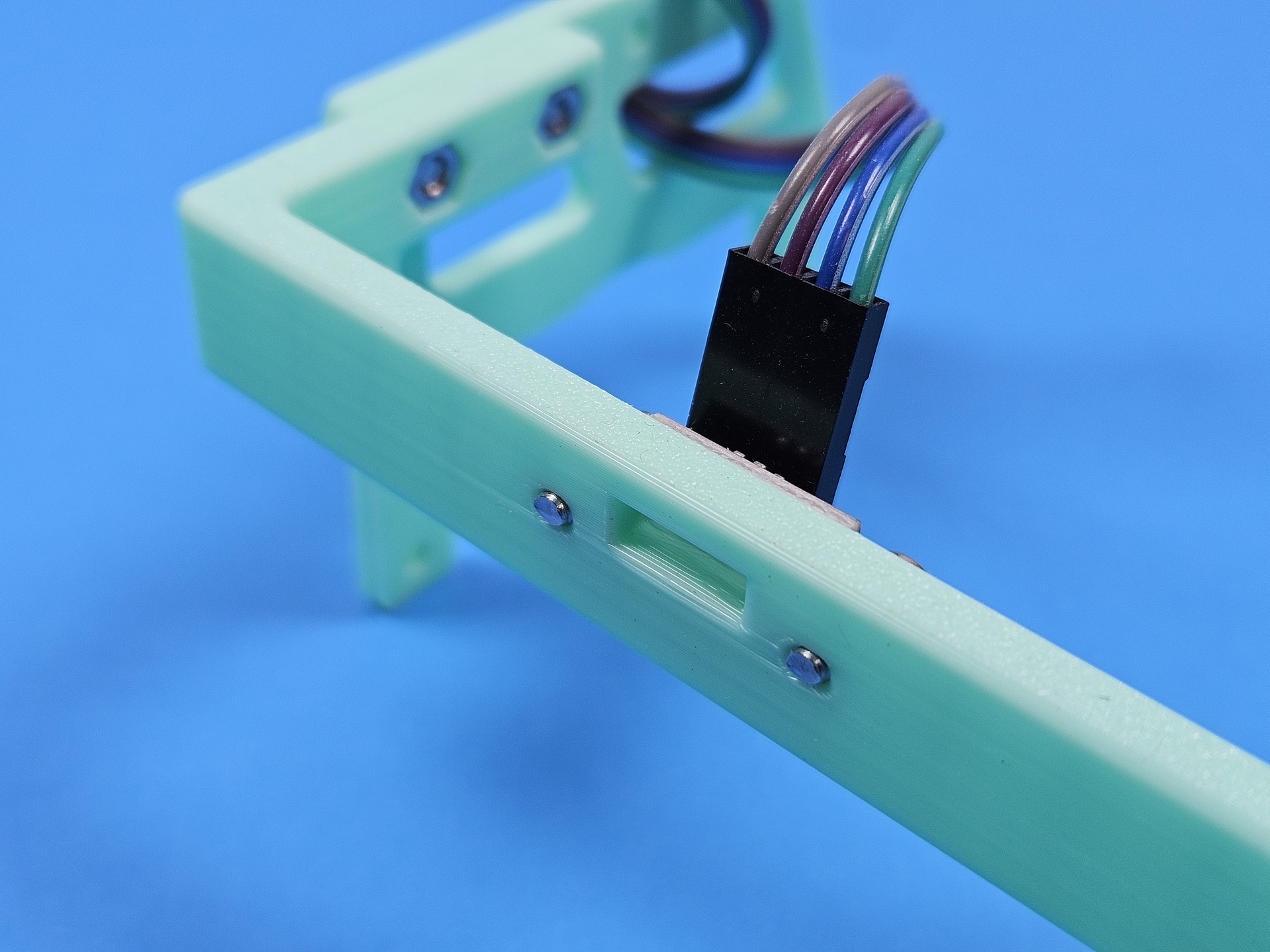
The VL53L0X board seated in the front crossbar.
Parts
CLICK TO ENLARGE

Parts

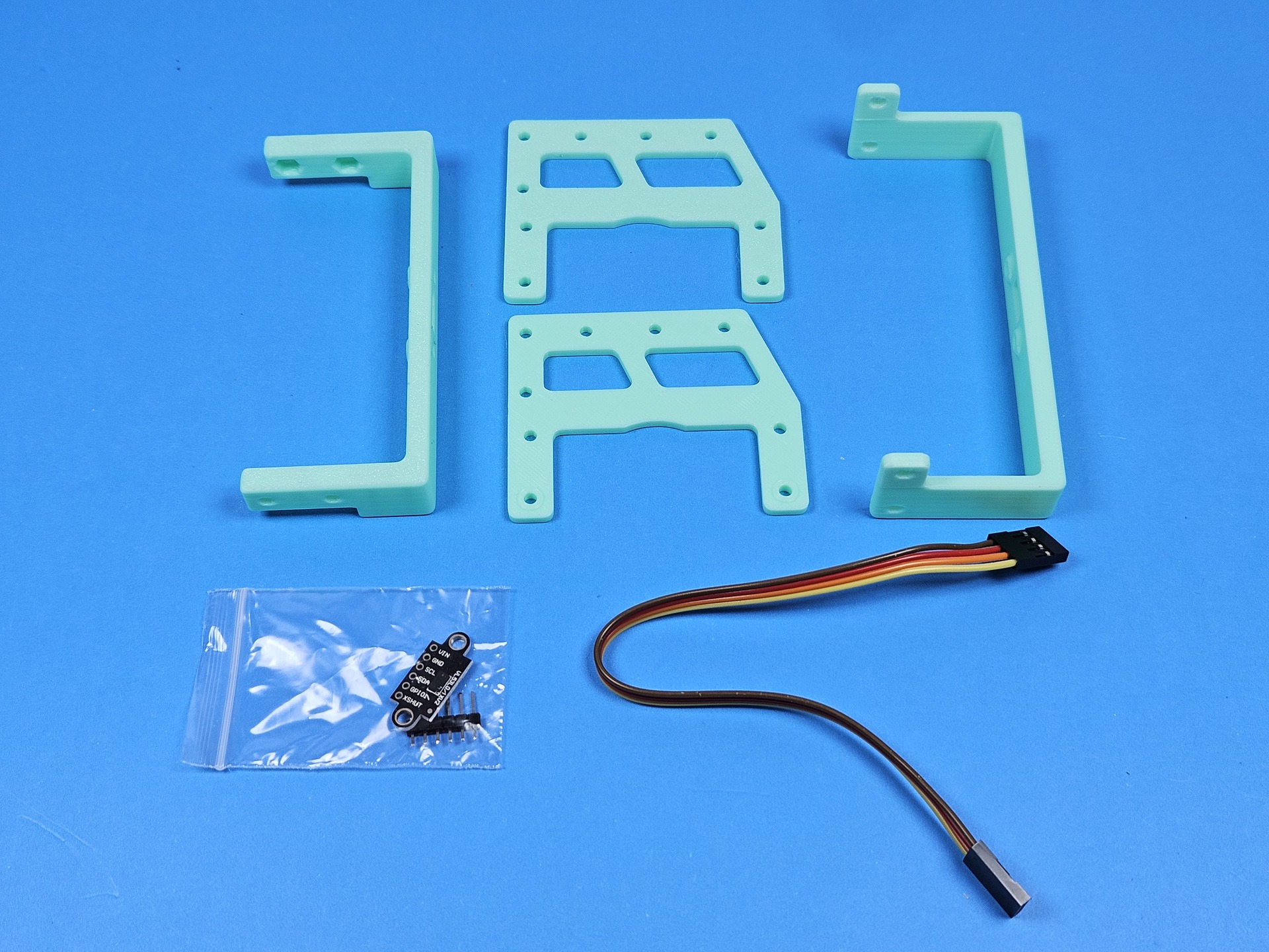
The printed plates, the sensor board, and the cable before assembly.
Frame
CLICK TO ENLARGE

Frame

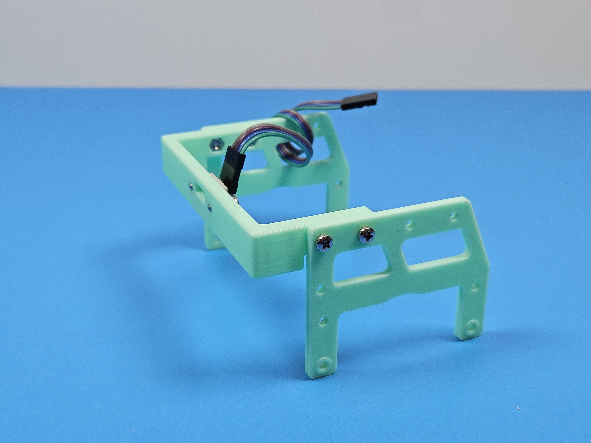
The side plates and crossbar screwed together, with the cable installed.
CAD on Stackr
CLICK TO ENLARGE

CAD on Stackr

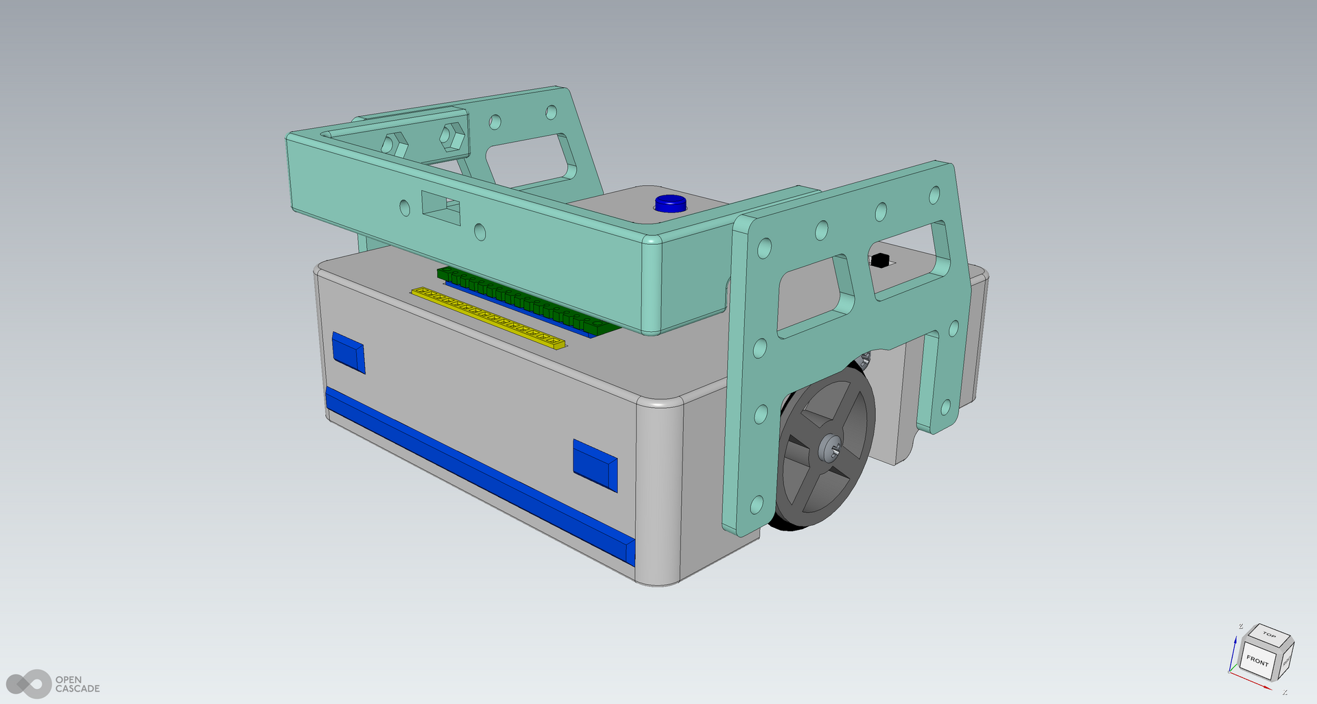
The FreeCAD model of the frame on the robot.
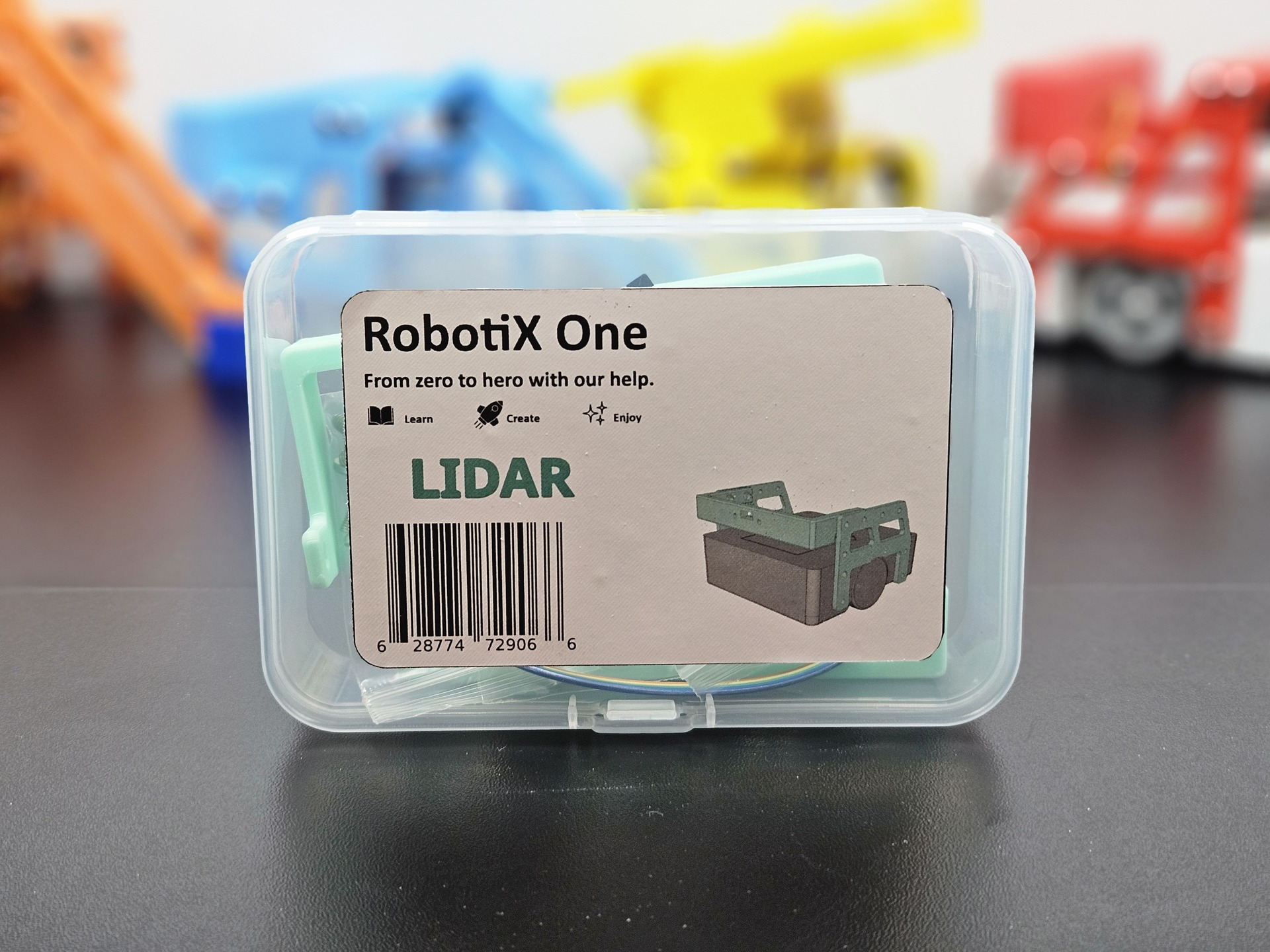
Kit
CLICK TO ENLARGE

Kit

The RobotiX One lidar kit, with the printed parts in the box.

// SLIDESHOW

All Project Pictures

12 photographs and drawings from this build.

20251107_214557.jpg 1 / 12
20251107_214557.jpg
// TECHNICAL SPECIFICATIONS

System Parameters & Metrics

PARAMETER SPECIFICATION / VALUE
Host Stackr
Sensor VL53L0X laser time-of-flight
Interface I2C, pins VIN, GND, SCL, and SDA
Mount Printed front frame and side plates
Cable Ribbon cable to the controller
Design FreeCAD assembly